Independent engineering laboratoryBologna · Italy

From antenna
to bits.

RF, professional wireless audio and electronic systems engineered across the complete signal chain — from architecture and hardware to measurement and production.

10 MHz–6 GHzLow- and high-power RF systems
470–870 MHzProfessional wireless audio expertise
R&D → MPDesign through production
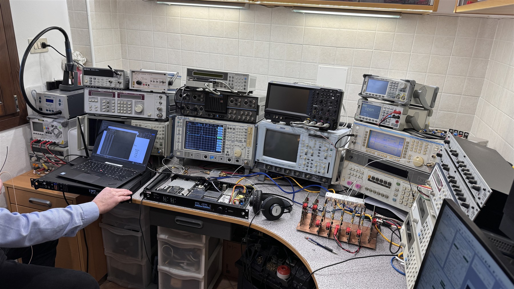
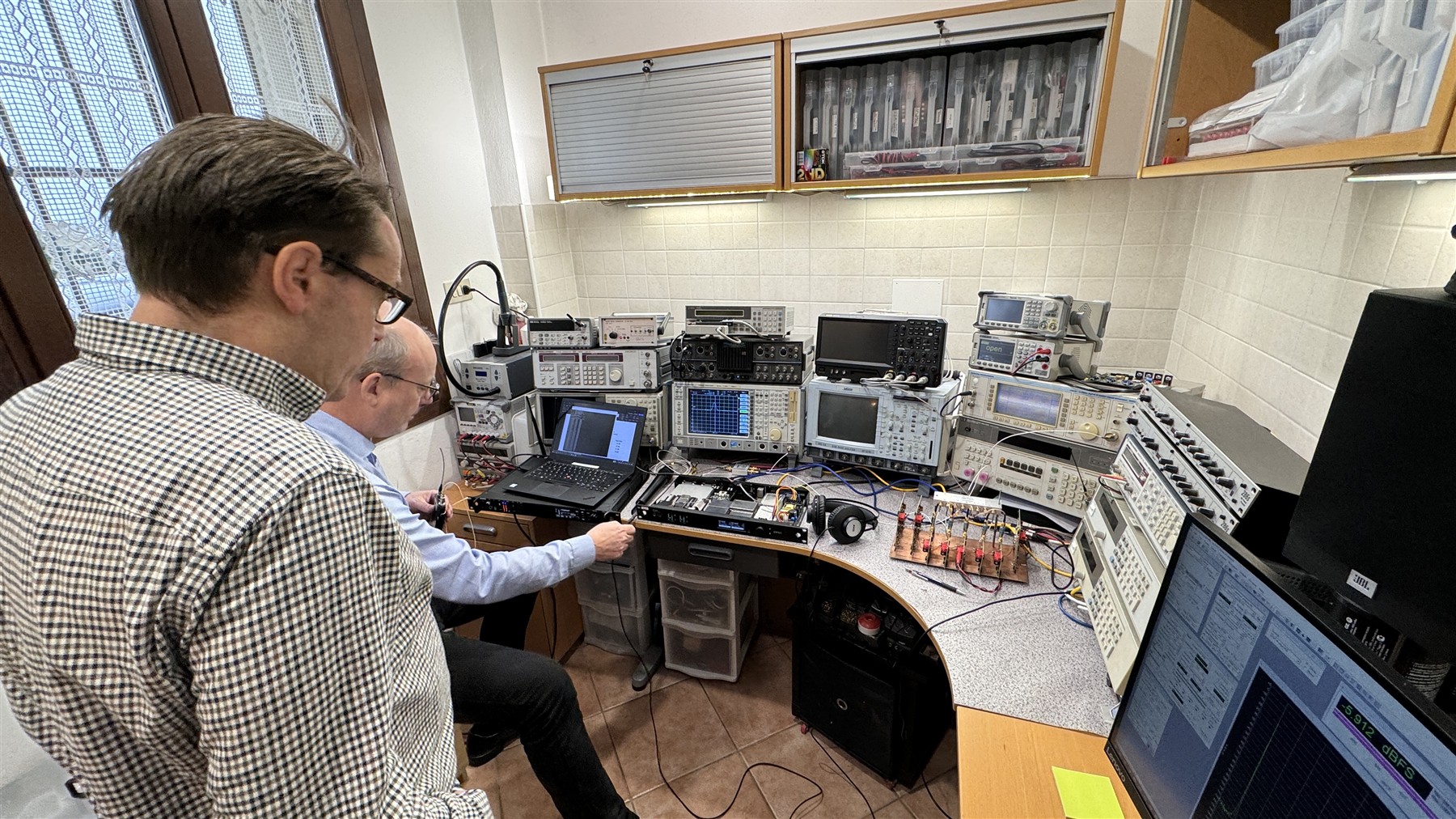
RF and audio measurement laboratory with engineering instruments
01 In-house RF & audio laboratory
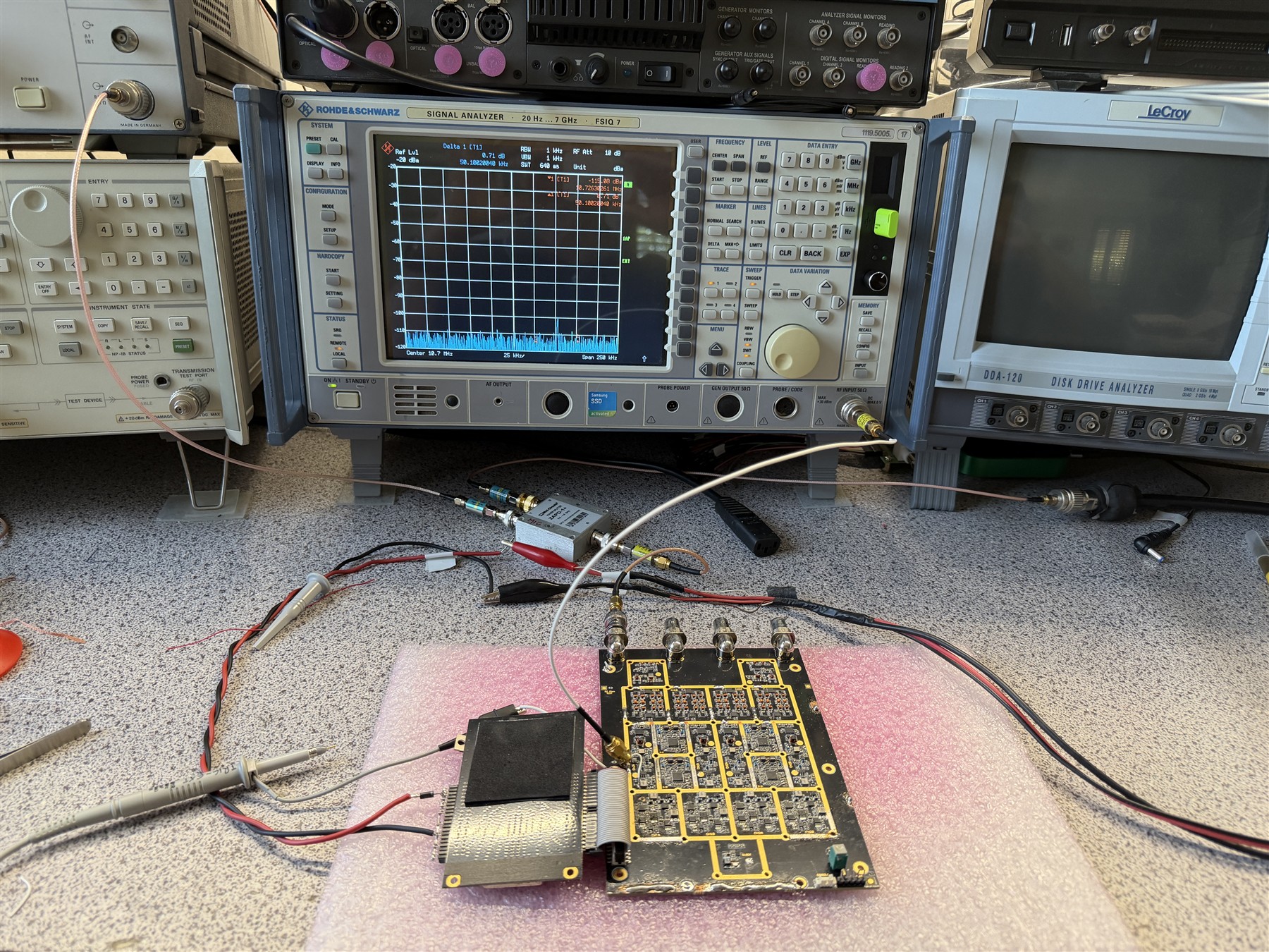
RF circuit under measurement on a laboratory bench
Measured, not assumed

01 / ENGINEERING APPROACH

Architecture first.
Physics always.

Logic Design Lab is built around direct engineering responsibility: system decisions are followed through circuit design, FPGA implementation, prototype bring-up, laboratory validation and the realities of repeatable manufacturing.

02 / CORE CAPABILITIES

The complete
signal chain.

A compact laboratory with system-level reach. The work stays connected from RF propagation to recovered data, from the noise floor to the production test bench.

01

RF / WIRELESS

Wideband RF systems & antennas

Transmitters and receivers, frequency synthesis, low-noise front ends, switched filtering and wideband PCB antennas developed as one coherent RF architecture.

  • 470–870 MHz platforms
  • PLL / VCO
  • PCB antennas
  • Sonnet EM
  • Dense multichannel RF

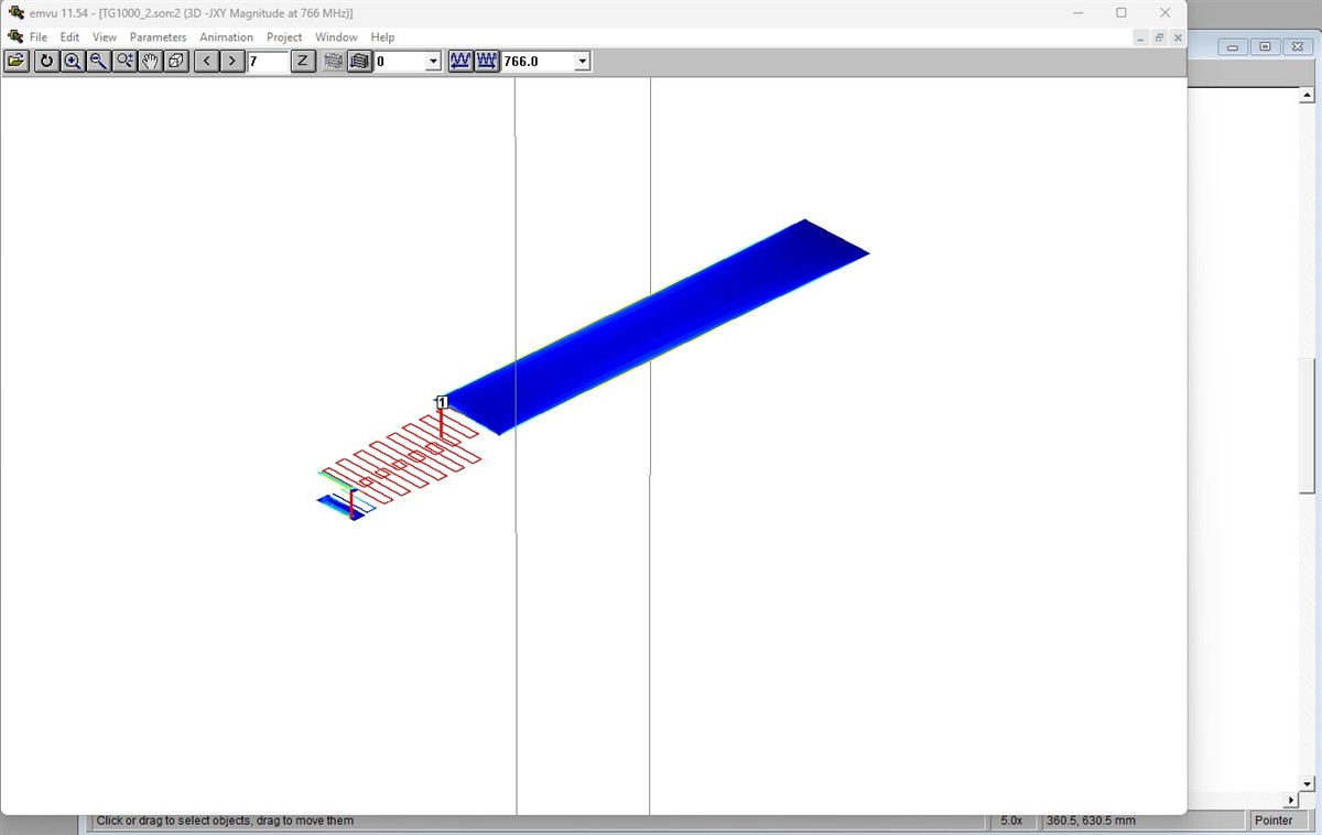
SONNET EM Wideband TX PCB antenna development

Sonnet electromagnetic model and surface-current simulation for a wideband transmitter PCB antenna
EM model / current distribution
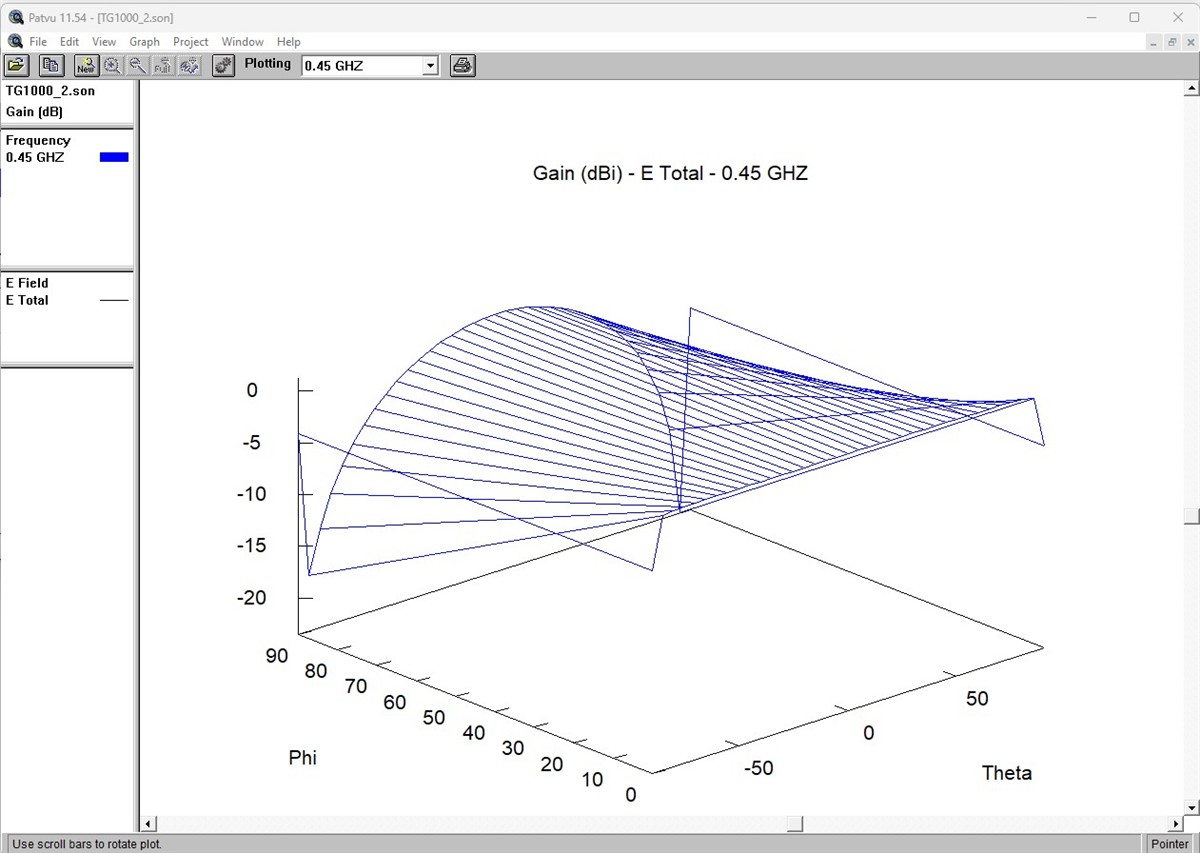
Sonnet three-dimensional antenna gain simulation
Radiation pattern
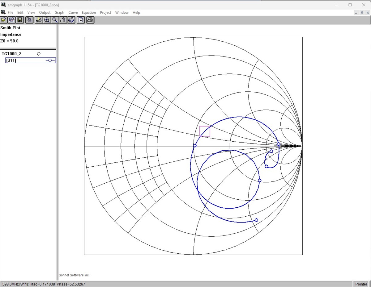
Sonnet Smith-chart impedance simulation
Impedance
02

ANALOG / AUDIO

Low noise. Low distortion. Real headroom.

Microphone-quality analog paths, ADC/DAC integration, clocking and power architectures verified with precision audio measurement.

126 dBsystem dynamic range achieved in a production wireless platform
03

FPGA / DIGITAL LINK

Protocols built around the channel.

Proprietary over-the-air framing, modulation and demodulation logic, clock recovery, encryption integration and receiver data paths.

04

EMBEDDED INTEGRATION

Hardware and firmware meet at defined interfaces.

Board-level drivers, STM32 low-level debugging and detailed DSP/firmware specifications aligned with the radio protocol and hardware timing.

  • Embedded C
  • Drivers
  • STM32 debug
  • DSP specification
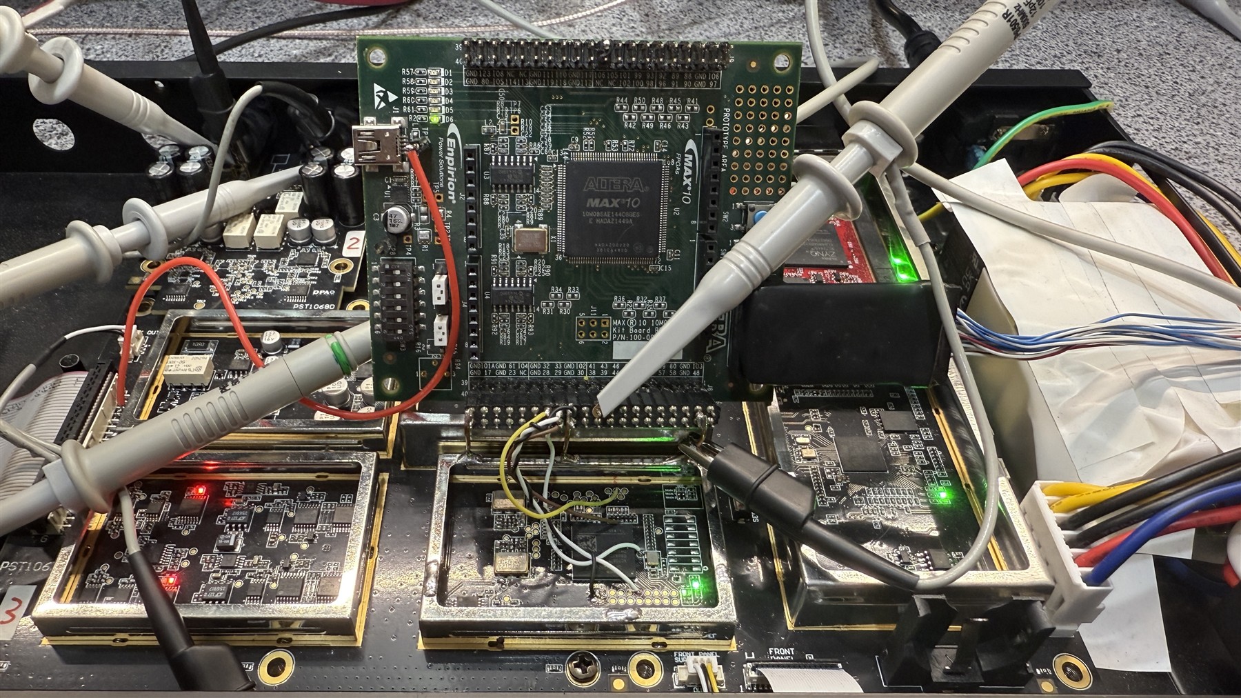
Wireless audio prototypes undergoing RF measurements
05

BRING-UP / DEBUG

Prototype reality.

What simulation predicts is challenged at the bench — early, repeatedly and with the right instrument.

06

INDUSTRIALIZATION

Engineering does not stop at the working prototype.

Design-for-test, automated GPIB procedures, fixtures, calibration, quality-control documentation, operator training and direct production transfer in Europe and Asia.

R&DPILOTMPQC

03 / SELECTED SYSTEMS

Engineered into
real products.

The most meaningful specification is a system that survives the stage, the spectrum and the production line. Selected architectures developed through Logic Design Lab have been commercialized internationally.

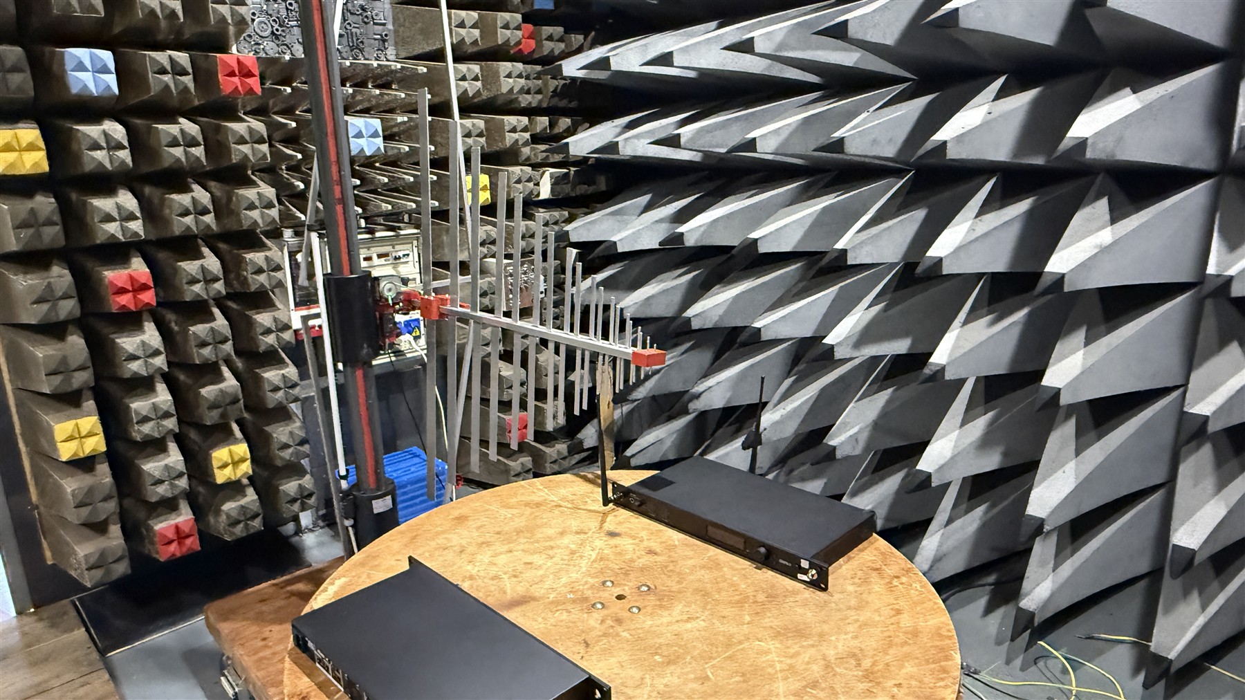
Professional digital wireless receiver under test in an RF anechoic chamber RF anechoic validation / production system

Current productionMajor professional audio brand

High-end digital wireless microphone system

A professional digital wireless audio platform designed for high channel density, difficult RF environments and uncompromised microphone performance.

Tuning range
470–870 MHz
Audio
126 dB dynamic range
Security
AES encrypted audio
Scope
System architecture · TX/RX hardware · RF · analog · FPGA protocol
Engineering note +

The RF link, wideband transmitter, switched output filtering, PCB antenna, low-noise audio path, over-the-air protocol and FPGA clock-recovery architecture were developed as a single system. DSP firmware was implemented by specialized developers from the detailed protocol and hardware requirements supplied by Logic Design Lab.

2009dBTechnologies

DWS800 / RS16000 Touring Rack

Patented digital wireless platform with 400 MHz switching bandwidth, later evolved into the RS16000 touring-rack system with dedicated PC control software and Ethernet configuration.

  • 470–870 MHz
  • Proprietary digital radio protocol & FPGA clock recovery
  • Dedicated PC software / Ethernet
  • Production transfer in China
Patent WO 2012/131735 ↗

Professional wirelessbeyerdynamic

TG1000 / TG500

Digital and high-end analog wireless microphone platforms developed through a mixed Italian–German engineering collaboration.

  • 400 MHz tuning range
  • High-quality digital audio
  • Complete RF hardware
  • German / Italian production support

2005RCF

Forum conference system

Large digital conference architecture with central management, networked consoles and an encrypted radio interpretation system.

  • Up to 250 consoles
  • RJ45-connected digital consoles
  • Automatic console updates
  • Multichannel encrypted UHF interpretation
First page of patent WO 2012/131735

04 / ORIGINAL IP

A wideband idea,
made manufacturable.

Patent WO 2012/131735 covers the digital microphone radio transmission architecture developed for the DWS800 platform and its later RS16000 touring-rack evolution. The invention addressed wide tuning, RF performance and practical product implementation as one problem.

InventorMichelangelo Carrozzo
PublicationWO 2012/131735 A1
ApplicationPCT/IT2011/000098
Open the WIPO record

05 / THE LABORATORY

Design is a hypothesis.
Measurement is the answer.

IN-HOUSE MEASUREMENT

The bench closes the loop.

Direct access to RF and audio instrumentation makes iterative debugging part of the design process, not an outsourced final check.

  • RFVector signal analysis to 7 GHz
  • S-PARAMETERSVector network analysis to 6 GHz
  • STIMULUSVector signal generation to 5.4 GHz
  • AUDIOAudio Precision System Two · full option set
  • DIGITALOscilloscopes · protocol analysis · low-level debug
  • AUTOMATIONGPIB test and production procedures

06 / WORKING METHOD

One continuous
engineering loop.

Small by design, the lab keeps technical judgment close to the hardware while integrating with specialist firmware, mechanical and manufacturing teams when the system requires it.

  1. 01

    Define

    System architecture, RF budget, audio targets, interfaces and constraints.

  2. 02

    Simulate

    Circuit behaviour, modulation, RF networks, antennas and electromagnetic structures.

  3. 03

    Build

    Schematics, PCB, FPGA logic, drivers and the first complete signal path.

  4. 04

    Measure

    Bring-up, correlation, interference analysis, audio performance and RF resilience.

  5. 05

    Transfer

    Test strategy, fixtures, procedures, training and production supervision.

07 / TECHNICAL ROOTS

Built by explaining
how things work.

Logic Design Lab was founded in 2000 by Michelangelo Carrozzo after decades of hands-on work in radio and five years as Editorial Director and electronics designer at the Italian technical magazine Nuova Elettronica.

That editorial discipline remains part of the laboratory’s engineering culture: a circuit should not only work. Its operating principles, trade-offs and failure modes should be understandable.

AES Michelangelo Carrozzo is an active member of the Audio Engineering Society.

“The point where a simulation finally agrees with the measurement bench is still the most interesting part.”

1995—2000

Nuova Elettronica

RF transmitters and receivers · PLL theory · laboratory instruments · precision measurement · tube hi-fi · TTL and CMOS fundamentals

08 / CONTACT

Have a difficult
signal path?

Start with the engineering problem. The useful conversation usually begins before the schematic.